|
|
You are here: Foswiki>CleanroomTestStands Web>SetupTCT (31 Mar 2022, SvenWonsak)Edit Attach
TCT Setup
TCT Data Aquisition TCT Data Analysis
Update for Windows 10
Particulars software download page- SMC-Win7-Win10-Migration.pdf: Stage Migration from Windows 7 to Windows 10
Particulars Setup
Homepage of Particulars: http://www.particulars.si/ additional informations / manuals / software can be accessed via this homepage ScanTCT_Install.pdf: Installation ManualPeltier
- max. 15.4 V and 8.5 A
- Pt100_connection.pdf: Pt100 connection
- Particulars-MountingPlane.pdf: Dimensioned drawing of mounting plane (Particulars)
Laser
Combine laser head and driver in the single housing- optics system preinstalled: iris, lens, beam expander, collimator, fibre connector
- focal distance of optics system: 8.4 - 8.5 cm
- short pulses (350 - 400 ps) with puls energy corresponding to ~ 1000 MIP
- LA-01 IR; 1060 nm, 100mW
- pulse width: 100% = threshold at the output stage is at the limit of operation
- 100% narrowest possible pulse (also low intensity) (3.3V from DAC)
- 10% very wide and intense pulse
- ParticularsLaserControl-UserGuide.pdf: Laser Control User Guide
- ParticularsLaserHardware-UserGuide.pdf: Laser Hardware User Guide
- ParticularsProcedures-FocusFind.pdf: Procedures Focus Find
- Particulars-Procedures-LaserPulse.pdf: Procedures Laser Pulse
Bias-T
BT-01- max applied voltage: 1-2 kV
- leakage: <500 nA @ 1 kV
- frequency range: lower end <100 kHz; hi end >2000 mHz
- input/output impedance: ~50 ohm / ~50 ohm
- Bias-T_Specs.pdf: BiasT specs
Amplifier
AM-01 A- bias voltage: 6-15 V
- amplification: 35dB, 53dB
- frequency range: 0.01 - 2000 MHz
- input/output impedance: ~50 ohm / ~50 ohm
- amplifier_Specs.pdf: Amplifier specs
Motion Stage
- X, Y, Z stage with range from 0 to 52000 um
- Old Control software (uSMC):
- New Control software available:
Additional Equipment
PC
- Windows PC:
| Standard HEP Case, PSU and motherboard | |
| 16 GB Memory | i7-3770 3.4GHz QuadCore CPU |
| 2TB WD Hard drive | 250 GB SSD |
| GT640 2GB | |
| Microsoft keyboard+Mouse | DVD-RW |
| Asus 27" monitor | http://www.asus.com/Monitors_Projectors/MX279H/ |
| Cost £938.00 including delivery (+VAT). | |
- need LabView V10 or higher and Microsoft Visual C++ VS 2008
- both provided in managed Windows of the University (MWS)
Managed Windows hints
- change power settings:
- 'Set Power-saving level' in 'Install University Applications'
Oscilloscope
- required:
- driver for LeCroy, Textronix
- communication over GPIB
- 4 channel, 1GHz, 5 GS/s
DRS evaluation board
- recommended: 4 channel, 1GHz, 5 GS/s digitization board from PSI (http://www.psi.ch/drs/evaluation-board)
- Four 50-Ohm terminated input channels with SMA connectors.
- Active input buffers which result in an analog bandwidth of 700 MHz (-3dB).
- High bandwidth analog switches for internal voltage calibration.
- Precision clock for internal timing calibration, reaching a precision of a few pico seconds.
- One DRS4 chip, capable of sampling the four input signals simultaneously from 0.7 GSPS to 5 GSPS with 1024 sampling points each.
- One AD9245 ADC to digitize signals from the DRS4 chip.
- One Xilinx Spartan 3 FPGA for readout control.
- A 16-bit DAC to generate all on-board control voltages.
- A serial EEPROM containing serial number and calibration information.
- Internal trigger with user-defined thresholds on any of the four channes.
- Triggering on combinations of the four channels (AND/OR) for coincidence measurements.
- An external trigger input (TTL input 50 Ohm terminated) with a MCX connector.
- Clock input and output connectors (MCX) for synchronizing several evaluation boards.
- A USB 2.0 interface for data readout. This interface also powers this board. The maximum readout rate is about 500 events per second.
- Several headers for debugging of all important control signals with an oscilloscipe or logic analyzer.
- DRS4_manual_rev50.pdf: Evaluation Board Manual
- DRS4_rev09.pdf: DRS4 chip specifications
- offer: 900EUR
- from manual:
- sampling speed up to 5 GSPS and 1024 sampling points
- SMA connectors for 4 input channels, MCX connectors for triggering and clokc synchronization, powered through USB
- inputs AC coupled and input range of 1V peak-to-peak
- maximum allowed input voltage:
- DC: +- 10 V
- Long pulse (<2us): +- 20 V
- Short pulse (<200ns): +- 30 V
- USB 2.0 bus allows data transfer rates of more than 20 MB/sec
O/E Converter
- TTI Model TIA-950 O/E Converter
- TIA950Manualforscreen.pdf: TIA-950 Manual
- InGaAS (900-1700nm)
- Post amplifier gain: 1.0, 10.0 selsctable
- Max. linear input power: >0.8mW
- Max. input power without damage: 10mW
- Bandwidth (-3dB): DC to 750 MHz at gain of 1.0, DC to 250 MHz at gain of 10.0
- Output impedance: 50 ohms
- Output connector: BNC
- Fibre optic input connector: FC
- Input numerical aperture: 0.29
- Interstage coupling: AC or DC (100Hz frequency cut off)
- Output offset voltage: < +/- 0.75 V at max. gain
- Max. output voltage: 2 V pk-pk, no load, 1V pk-pk with 50 ohm load
- Noise level: 3 pW/Hz^1/2
- Power required: 9 V battery powers the unit for approx. 30 hrs (no load)
Amplifier Power
- TTi PL310
- 32V - 1A PSU
High Voltage
- Keithley 2410 1100V SourceMeter
- GPIB / RS-232 connector
- GPIB to USB convertor
- NI GPIB-USB-HS
- NI_GPIP-to-USB-HS.pdf: GPIB-to-USB manual
PID
- Laird TC-XX-PR-59
- PWM Programmable PID Controller £ 236.00 / each (31/10/14)
- PT1000 temperature sensor for temperature measurement
- RS232 output
- Voltage nominal: 0 - 15V
- max. 15A without cooling
- Drawing.pdf: PID controller drawing
- GettingStarted.pdf: PID controller Getting Started
- NTC.pdf: NTC
- SC_Interface.pdf: SC_Interface
- SC_Interface_Help.pdf: SC_Interface Help
- THR-DS-TC-XX-PR-59_1012.pdf: PID controller data sheet (PT1000)
- Laird.zip: PID controller software (Laird)
- supercool_PR59.zip: CERN PID controller software (Christian Gallrapp) ( LabView 11)
- supercool_PR59_SSD_Software.lvlib: CERN PID controller Softwar (LabView 14)
PID settings
| PID | CERN | Freiburg |
Default |
|---|---|---|---|
| Integral Value Limit | 100% | 100% | 100% |
| Max Power | 100% | 100% | 100% |
| kP | 6.31 | 30 | 20 |
| kD | 4 | 20 | 5 |
| Dead band | 3% | 3% | 3% |
| Lowpass Tr | 2 | 2 | 2 |
| Lowpass Te | 3 | 2 | 3 |
| kI | 0.012 | 1 | 2 |
| Cooling Gain | 1 | 1 | 1 |
| Heating Gain | 1 | 0.5 | 1 |
| Decay when stopped | 0.1 | 0.1 | 0.1 |
- Peltier:
- RS: (peltiers tested at CERN)
- 112.7W Peltier Module, 6A, 29.8V £ 55.40 / each (27/11/2014); used by CERN TCT+
- 340.5W Peltier Module, 15.4A, 35.8V £ 153.13 / each (27/11/2014); high power peltier
- to use these peltiers a appropriate power supply (higher output power) is needed
- RS: (peltiers tested at CERN)
Peltier Power
- EA Power supply EA-PS-2042-10B
- 160W 1 Output Digital Bench Power Supply, 0 to 42V, 0 to 10A £ 212.10 / each (12/01/2015)
PCB
- to place sensor
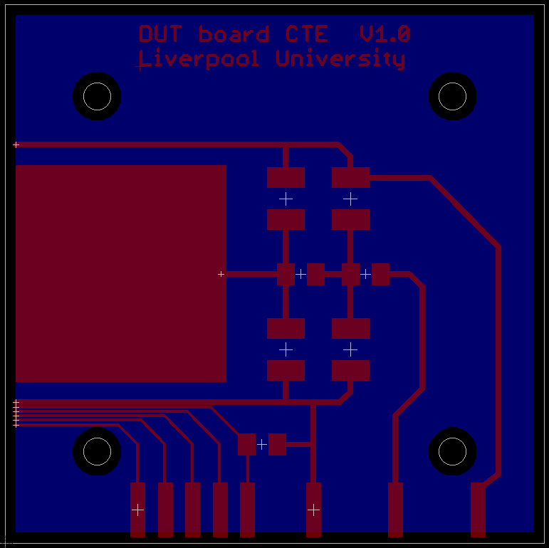
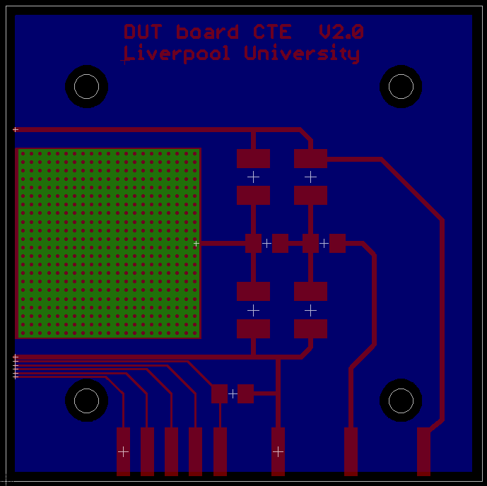
Liverpool 1
- two versions designed by Ilya Tsurin; 4 each produced (£123.00 including delivery and VAT):
| Version 1: single layer | Version 2: vias to sensor backplane for better heat transfer |
 |
 |
| PCB Version 1 | PCB Version 2 |
-
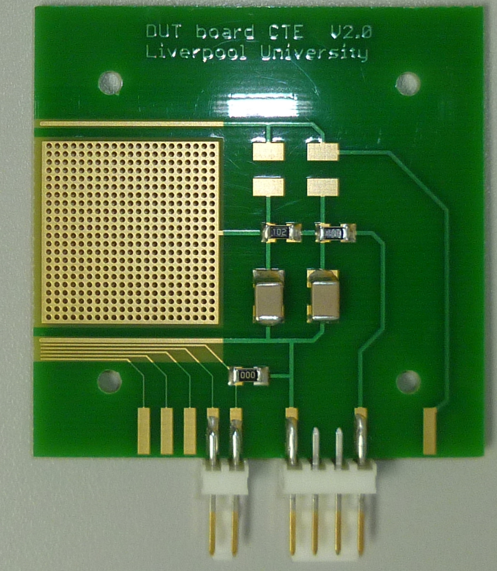
- components:
- YAGEO (PHYCOMP) - CC1812KKX7RDBB103 - CAP, MLCC, X7R, 10NF, 2KV, 1812 £ 1.31 / each (05/11/14)
- MULTICOMP MCMR12X102 JTL RESISTOR, ANTI SULFUR, 1K, 1206, 5% £ 0.0097 / each (min 100) (09/01/2015)
- MOLEX - 22-29-2041 - CONNECTOR, HEADER, THT, 2.54MM, 4WAY £ 0.464 / each (05/11/14)
- MOLEX - 22-01-2045 - CRIMP HOUSING, 2.54MM, 4WAY £ 0.21 / each (05/11/14)
- MOLEX - 22-29-2021 - HEADER, VERTICAL, SQ PIN, 0.1", 2WAY £ 0.26 / each (05/11/14)
- MOLEX - 22-01-2025. - CRIMP HOUSING, 2.54MM, 2WAY £ 0.142 / each (05/11/14)
- MOLEX - 08-55-0102 - TERMINAL, SOLDERLESS, 24AWG £ 0.125 / each (05/11/14)
- components:
 PCB-V2.jpg: Populated PCB (V2.0)
- PCB-Liverpool.pdf: Manual for Liverpool PCB (wirebonds).
DESY
Designed at DESY for the measurements of diodes and strip sensors.- 9231-00_Produktions_daten1.zip: Files for DESY PCB
Liverpool 2
Designed at Liverpool by Samuel Powell for measuring HV-CMOS sensors. The PCB fits the particulars cold chuck mount.- HVCMOS-PCB-connection.pdf: Liverpool HV-CMOS PCB pinout
- HVCMOS-PCB2-connection.pdf: H35DEMO TCT PCB
Mechanical changes to setup
For edge TCT measurements a 90 degree angle mount was designed, which allows to mount the cold chuck so that the laser hits the sensor edge. Because of the additional height difference to the laser line, a base plate for lifting the laser was designed as well. This plate has to be placed under the motion stage plate for the laser optics and should be screwed to the bottom of the box. The angle mount can be screwed to the motion stage instead of the '3UBP - Universal Base Plate'- AnglePlate.pdf: 90 degree angle mount for cold chuck
- Laser_Groundplate.pdf: Ground plate for Laser (edge TCT)
Required equipment
Chiller
- should be USB controllable
- -40C ... ~+40C
- Huber Minichiller EUR 2230.00 (15/04/15)
- Huber MPC-K6 EUR 2700.00 (15/04/15)
- Huber Chiller list
- Huber Chiller list 2
- Liverpool Clean room (other set-ups)
- Thermo NESLAB RTE 740
- Julabo F32
- CERN
- Huber CC 505
- Huber Unichiller
- pipes and connectors
- RS:
- RS PVC 30m Long transparent Flexible Tube, 64mm Bend Radius £ 10.67 / each (30m) (07/01/2015)
- RS:
Cold Block
- PT1000 temperature sensor and connector
- RS: Molex SL Series, Series Number 70543, 2.54mm Pitch 3 Way 1 Row Straight PCB Header, Solder Termination, 3A £ 0.618 / each (pack of 5) (08/01/2015)
- Farnell: IST INNOVATIVE SENSOR TECHNOLOGY P1K0.232.6W.A.010 £ 7.18 / each (24/11/2014) for IV measurements
- Particulars-MountingPlane.pdf: Drawing of Mounting Plane
- RS Nylon Screw Insulator, M4, 3mm £ 2.75 / each (bag of 50) (09/01/2015)
- Plain Nylon Cheese Head Machine Screw, M4 x 20mm £ 6.58 / each (bag of 100) (09/01/2015)
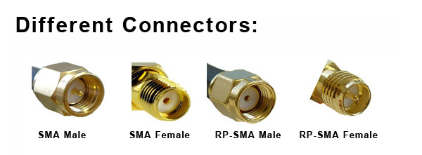
Cables / Connectors
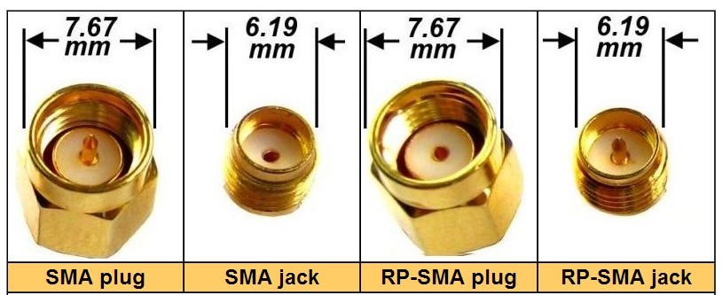
 SMA genders
 SMA genders 2
- SMA cables and connectors
- RS:
- SMA plug end termination,1W DC to 2.5GHz, (m) £4.46 / each (22/09/2014)
- Adapter SMA(F) to SMA(F) £ 2.90 / each (22/09/2014)
- SMA straight plug-plug RG174 RF cable,1m £ 11.67 / each (31/10/14)
- Mobilemark 50 Ω, Male SMA to Male RP SMA, Coaxial Cable Assembly 3m £ 22.00 / each (31/10/14) 1 end Reverse Polarity
- Straight 50Ω RF Adapter SMA RP Female to SMA Female £ 4.88 / each (01/06/17)
- Cable Assembly SMA M/M Straight/R Angle £ 15.26 / each (04/11/14)
- SMA plug to plug cable,50Ohm,RG-316,0.5m £ 15.96 / each (04/11/14)
- Adapter SMA(F) to BNC(M) £ 3.95 / each (05/11/14)
- Adapter SMA(M) to BNC(F) £ 3.95 / each (06/11/14)
- Adapter SMA(M) to SMA(M) £ 2.90 / each (06/11/14)
- Farnell:
- MULTICOMP - 19-21-1-TGG - ADAPTER, SMA JACK, SMA JACK, 50OHM £ 5.93 / each (31/10/14)
- AMPHENOL CONNEX - 132172 - ADAPTER, SMA JACK, SMA PLUG, 50OHM £ 6.67 / each (05/11/14)
- IST INNOVATIVE SENSOR TECHNOLOGY P1K0.520.6W.A.010 SENSOR, PT1000, 600°C, CLASS A £ 9.13 / each (24/11/2014)
- RS:
- other:
- RS: Black Euro converter mains plug 3A 600W £ 1.35 / each (24/09/2014) for ALiBaVa scintillator
- RS: RS 2 m Black Power Cable Assembly BS 1363 Plug 2.5 A to C5, 250 V £ 5.20 / each (22/09/2014)
Sensor polishing
- silver conducting lacquer (glueing sensor on PCB, but easy to remove, solvent with ethanol)
- Silver 5 g Bottle Paint Conductive Adhesive £ 16.94 / each (24/09/2014)
- Silver 20 g Bottle Paint Conductive Adhesive £ 46.20 / each (24/09/2014)
- diamond polish paste
- RS Grey Diamond Paste 1/10μm Grade
- RS order number: 315-5125
- RS Grey Diamond Paste 1/10μm Grade £ 13.60 / each (22/09/2014)
- diamond lapping film (still need to order)
- 3M Pink Diamond Fibre Optic Lapping Film, 280mm x 230mm, 3μm Grade
- RS order number: 296-0803 discontinued product
- Alternatives:
- 3M:
- Thorlabs link:
- LF3D - 6" x 6" Diamond Lapping (Polishing) Sheet, 3 µm Grit (5 Sheets) £28.44 / 5 sheets (22/09/2014)
- VRC2 - VIS/IR Detector Card, 400 - 640 nm, 800 - 1700 nm £ 55.19 / each (15/12/2014) laser detection card
- LG2 - Laser Safety Glasses, Green Lenses, 19% Visible Light Transmission, Universal Style £ 129.24 / each (16/12/2014) laser safety glasses
- 3M Pink Diamond Fibre Optic Lapping Film, 280mm x 230mm, 3μm Grade
- 2 bars to hold sensor during polishing process (CERN: teflon); bar width: 2 cm to clamp sensors which are larger than 1 cm. Use old silicon as distance holder (glued with Kapton inbetween bars).
- cotton bud (for polishing)
Remote Control
Teamviewer
Number: 110 434 409Personal Password: same as for 'anlg'
Tight VNC
WIN764-269292R .livad.liv.ac.ukPassword: same as for 'anlg'
Additional Recources (other Institutes)
Software
PID controller with LabView and TRACS simultion software from CERN SSD group:https://twiki.cern.ch/twiki/bin/view/SolidStateDetectors/SolidStateDetectorsSoftware
Weightfield2 simulation software:
http://personalpages.to.infn.it/~cartigli/Weightfield2/Main.html
KDetSim simulation software:
http://www-f9.ijs.si/~gregor/KDetSim/
Workshops:
1st TCT workshop at DESY (05-06/10/2015)https://indico.desy.de/conferenceDisplay.py?confId=12934 -- SvenWonsak - 17 Sep 2014


| I | Attachment | Action | Size | Date | Who | Comment |
|---|---|---|---|---|---|---|
| |
9231-00_Produktions_daten1.zip | manage | 1 MB | 23 May 2016 - 12:27 | SvenWonsak | Files for DESY PCB |
| |
AnglePlate.pdf | manage | 37 K | 14 Jul 2016 - 15:10 | SvenWonsak | 90 degree angle mount for cold chuck |
| |
Bias-T_Specs.pdf | manage | 273 K | 18 Sep 2014 - 13:00 | SvenWonsak | BiasT specs |
| |
DRS4_manual_rev50.pdf | manage | 9 MB | 24 Nov 2014 - 15:17 | SvenWonsak | Evaluation Board Manual |
| |
DRS4_rev09.pdf | manage | 350 K | 24 Nov 2014 - 15:17 | SvenWonsak | DRS4 chip specifications |
| |
DUT_CTE_board_V1.png | manage | 24 K | 31 Oct 2014 - 10:43 | SvenWonsak | PCB for sensor mounting |
| |
DUT_CTE_board_V2.png | manage | 23 K | 31 Oct 2014 - 10:43 | SvenWonsak | PCB for sensor mounting |
| |
Drawing.pdf | manage | 105 K | 20 Nov 2015 - 15:43 | SvenWonsak | PID controller drawing |
| |
GettingStarted.pdf | manage | 51 K | 20 Nov 2015 - 15:43 | SvenWonsak | PID controller Getting Started |
| |
HVCMOS-PCB-connection.pdf | manage | 512 K | 12 Aug 2016 - 09:56 | SvenWonsak | Liverpool HV-CMOS PCB pinout |
| |
HVCMOS-PCB2-connection.pdf | manage | 546 K | 12 May 2017 - 11:08 | SvenWonsak | H35DEMO TCT PCB |
| |
Laird.zip | manage | 2 MB | 04 Nov 2014 - 10:11 | SvenWonsak | PID controller software |
| |
Laser_Groundplate.pdf | manage | 17 K | 14 Jul 2016 - 15:11 | SvenWonsak | Ground plate for Laser (edge TCT) |
| |
NI_GPIP-to-USB-HS.pdf | manage | 370 K | 26 Nov 2014 - 09:47 | SvenWonsak | GPIB-to-USB manual |
| |
NTC.pdf | manage | 1 MB | 20 Nov 2015 - 15:43 | SvenWonsak | NTC |
| |
PCB-Liverpool.pdf | manage | 607 K | 09 Feb 2016 - 16:44 | SvenWonsak | Manual for Liverpool PCB (wirebonds). |
| |
PCB-V2.jpg | manage | 848 K | 09 Jan 2015 - 16:27 | SvenWonsak | |
| |
Particulars-MountingPlane.pdf | manage | 9 K | 19 May 2016 - 08:29 | SvenWonsak | Drawing of Mounting Plane |
| |
Particulars-Procedures-LaserPulse.pdf | manage | 611 K | 18 Sep 2014 - 13:01 | SvenWonsak | Procedures Laser Pulse |
| |
ParticularsLaserControl-UserGuide.pdf | manage | 917 K | 18 Sep 2014 - 13:01 | SvenWonsak | Laser Control User Guide |
| |
ParticularsLaserHardware-UserGuide.pdf | manage | 672 K | 18 Sep 2014 - 13:01 | SvenWonsak | Laser Hardware User Guide |
| |
ParticularsProcedures-FocusFind.pdf | manage | 663 K | 18 Sep 2014 - 13:01 | SvenWonsak | Procedures Focus Find |
| |
Pt100_connection.pdf | manage | 349 K | 18 Sep 2014 - 13:01 | SvenWonsak | PT1000 connection |
| |
SC_Interface.pdf | manage | 189 K | 20 Nov 2015 - 15:44 | SvenWonsak | SC_Interface |
| |
SC_Interface_Help.pdf | manage | 366 K | 20 Nov 2015 - 15:44 | SvenWonsak | SC_Interface Help |
| |
SMA-and-TNC-Connector1.jpg | manage | 45 K | 08 Jan 2015 - 11:00 | SvenWonsak | SMA genders 2 |
| |
SMA.jpg | manage | 70 K | 08 Jan 2015 - 10:55 | SvenWonsak | SMA genders |
| |
SMC-Win7-Win10-Migration.pdf | manage | 96 K | 04 Mar 2020 - 07:59 | SvenWonsak | Stage Migration from Windows 7 to Windows 10 |
| |
ScanTCT_Install.pdf | manage | 2 MB | 18 Sep 2014 - 13:23 | SvenWonsak | Installation Manual |
| |
THR-DS-TC-XX-PR-59_1012.pdf | manage | 945 K | 14 Apr 2016 - 13:31 | SvenWonsak | PID controller data sheet (PT1000) |
| |
TIA950Manualforscreen.pdf | manage | 201 K | 18 Sep 2014 - 08:37 | SvenWonsak | TIA-950 Manual |
| |
TTI_PL155-P_PowerSupply_Manual.pdf | manage | 5 MB | 04 Nov 2014 - 10:22 | SvenWonsak | TTI PL155-P Manual |
| |
amplifier_Specs.pdf | manage | 400 K | 18 Sep 2014 - 13:00 | SvenWonsak | Amplifier specs |
| |
supercool_PR59.zip | manage | 187 K | 04 Nov 2014 - 10:11 | SvenWonsak | CERN PID controller LabView software |
| |
supercool_PR59_SSD_Software.lvlib | manage | 883 K | 19 Nov 2015 - 10:02 | SvenWonsak | CERN PID controller Softwar (LabView 14) |
Edit | Attach | Print version | History: r56 < r55 < r54 < r53 | Backlinks | View wiki text | Edit wiki text | More topic actions
Topic revision: r56 - 31 Mar 2022, SvenWonsak
Ideas, requests, problems regarding Foswiki? Send feedback