The second and third solutions are unappealing for the reasons given
above. We have not investigated the fourth solution because of doubts
about what connectors could be effectively used.
Therefore, most of
our work concerns the first solution, and tries to arrange the hybirds
such that they will pass through the gap, while maintaining the smallest
possible cable lengths.
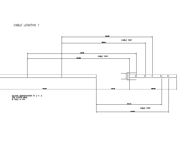
| For the 8-fold geometry, a possible layour for the hybrids is as shown. The silicon is 256 strips wide and there are 3 segments in z. Each segment is readout by one master and one slave. The total number of hybrids is 96. The longest cable is 475mm. There is the possibility of mounting one master-slave pair on the narrow part of the beam pipe, thus shortening the cables by 80mm. |
|
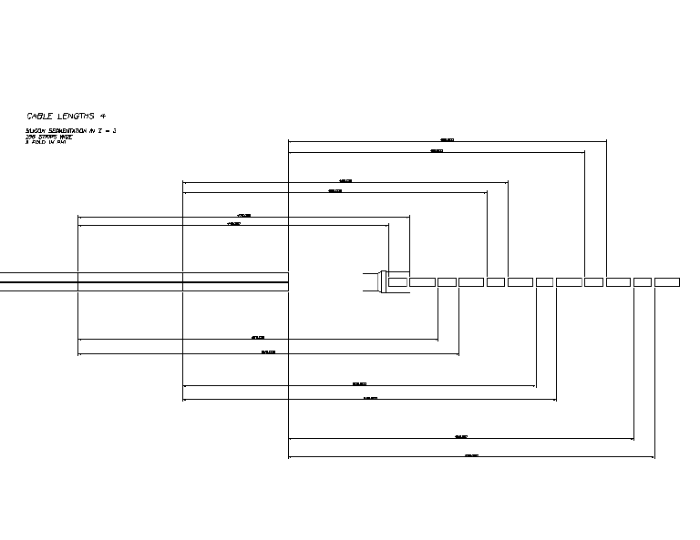
| This is a different arrangement for the hybrids on the 8-fold geometry which may be required if 8 hybrids can not fit around the beam-pipe. In this design, only 4 hybrids encircle the pipe. All the hybrids which read out two 256-strip ladders are placed in a single row, half way between both ladders. This increases the longest cable to 545mm. There are some nice structural features about this design in terms of supporting the silicon and introducing cooling, but it would also require `dog-legs' to be placed in the cables, in order to make the connections. |
|
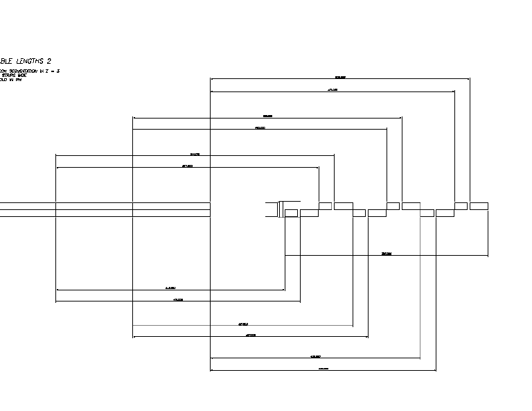
| A neater way of implementing the above ideas is shown here. Once again, only four hybrids encircle the beam-pipe, but every other pair of master and slave are offset and lined up with the ladder which they readout. The longest cable is 541mm. |
|
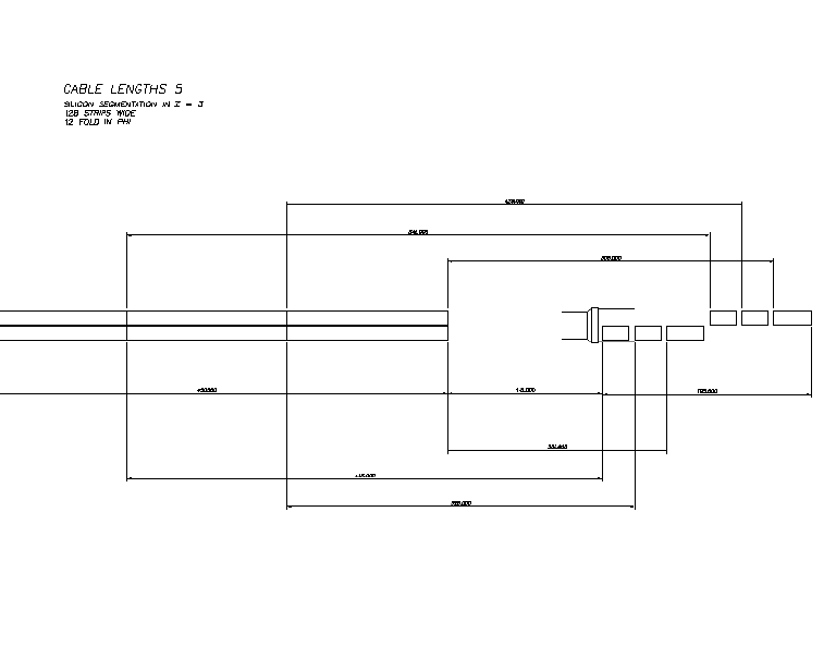
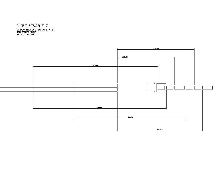
| We now turn to 12-fold geometries. Less hybrids (72) are required. However as the accompanying study shows this does not degrade the resolution: in fact it improves it considerably. A master and two slaves read out each ladder, one hybrid per z-segment. Each row of hybrids is aligned to a silicon ladder. Six hybrids fit around the beampipe. The largest cable length is 545mm. At the moment, this is our preferred solution. If one set of master-slave-slave can be placed on the narrow part of the beam-pipe, this will shorten the cable lengths by 110mm. |
|
| Alternatively, the hybrids can be arranged in a row, midway between the ladders. Structurely this has some benefits, but it makes the cable connections more difficult. There is now the freedom to read this out with 3 master-slaves, or 2 master-slave-slaves. The largest cable length is 475mm. |
|
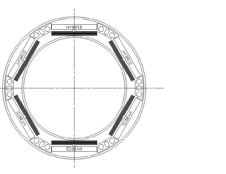
| This is the mechanical arrangement for inserting a 12-fold detector. Six detectors fit around the pipe and inside the SVX sleeve. Note that this assumes the hybrids are 1.5mm thick. This number needs clarification. If the hybrids are much thicker, it may not be possible to insert them in this manner. |
|
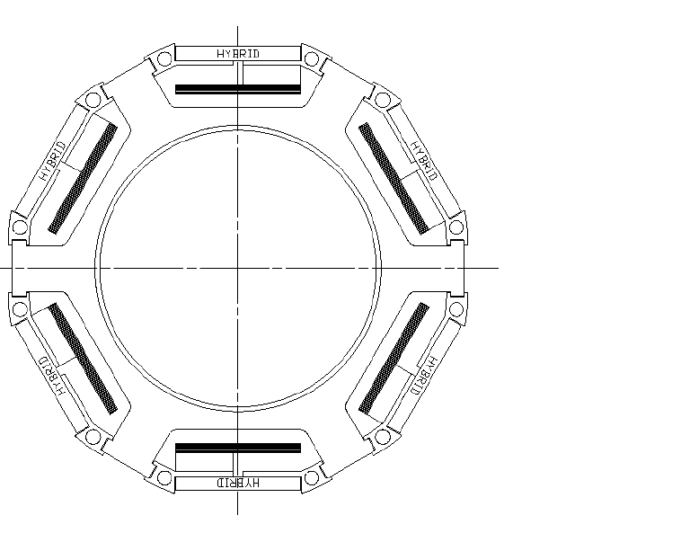
| After insertion, the hybrids can be opened out and placed on a support structure as shown. |
|