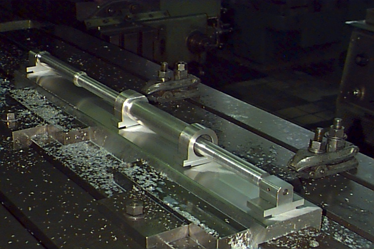
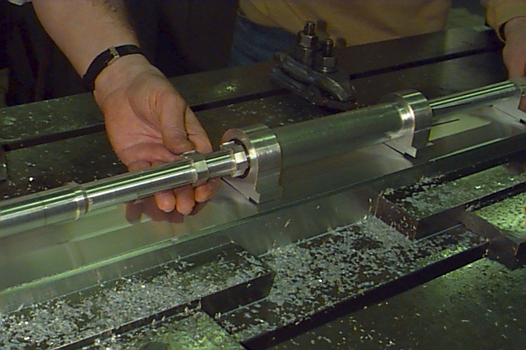
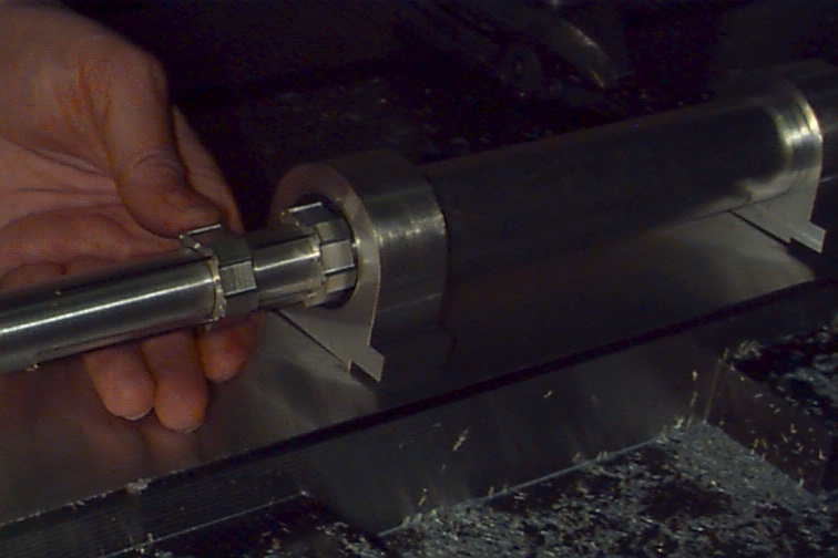
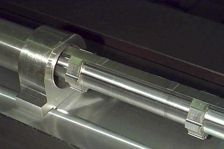
| The beampipe is mounted on a baseplate, and the inner sleeve of SVX2 is free to slide along, thus allowing us to check clearances. |
|
|
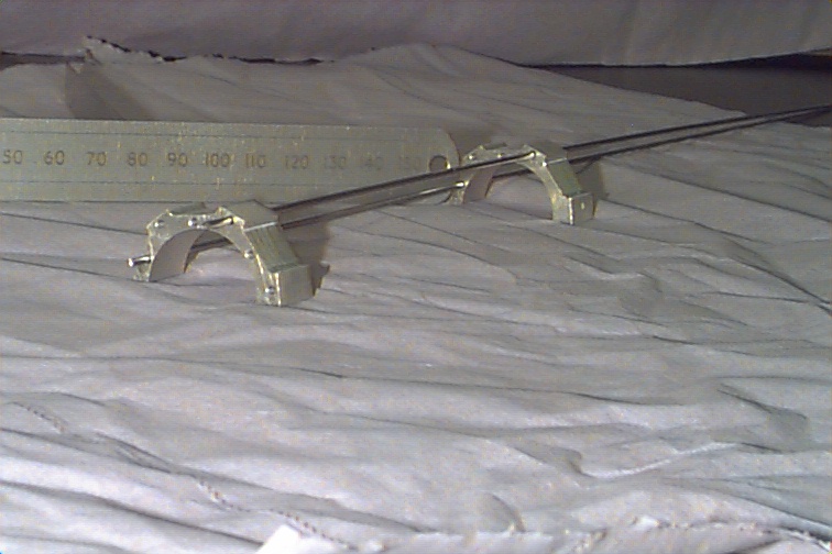
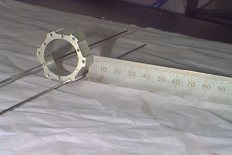
The clam-shells which would be made of carbon fibre and of length 45cm, are simulated by a series of precision cut aluminium half-rings, 1.5cm long. The holes in the rings are for cooling pipes. |
| |
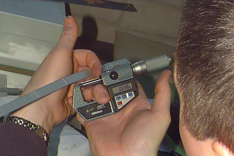
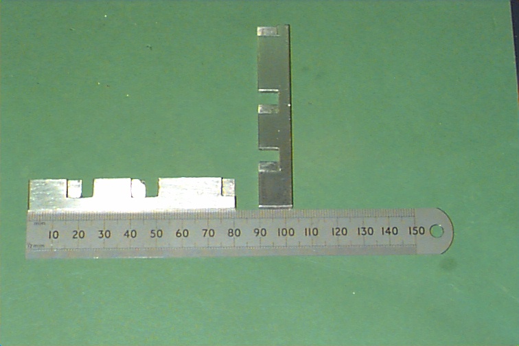
| The silicon ladders are simulated by 300 micron thick aluminium strips on which are glued small aluminium bumps to simulate the bond-wire heights. |
|
|
The hybrids are simulated using 500 micron thick aluminium representing the substrate with 2.0 mm high aluminium on top representing the components. Slots are cut in the baseplate to allow cables to come up from underneath. Our next task is to simulate the cable stacks using kapton. |
| The ladders and cables will be mounted on the clam-shells which will be placed around the beampipe. |
|
|
|
Back to Liverpool CDF Group Homepage
Maintained by mcnulty@hep.ph.liv.ac.uk